Background
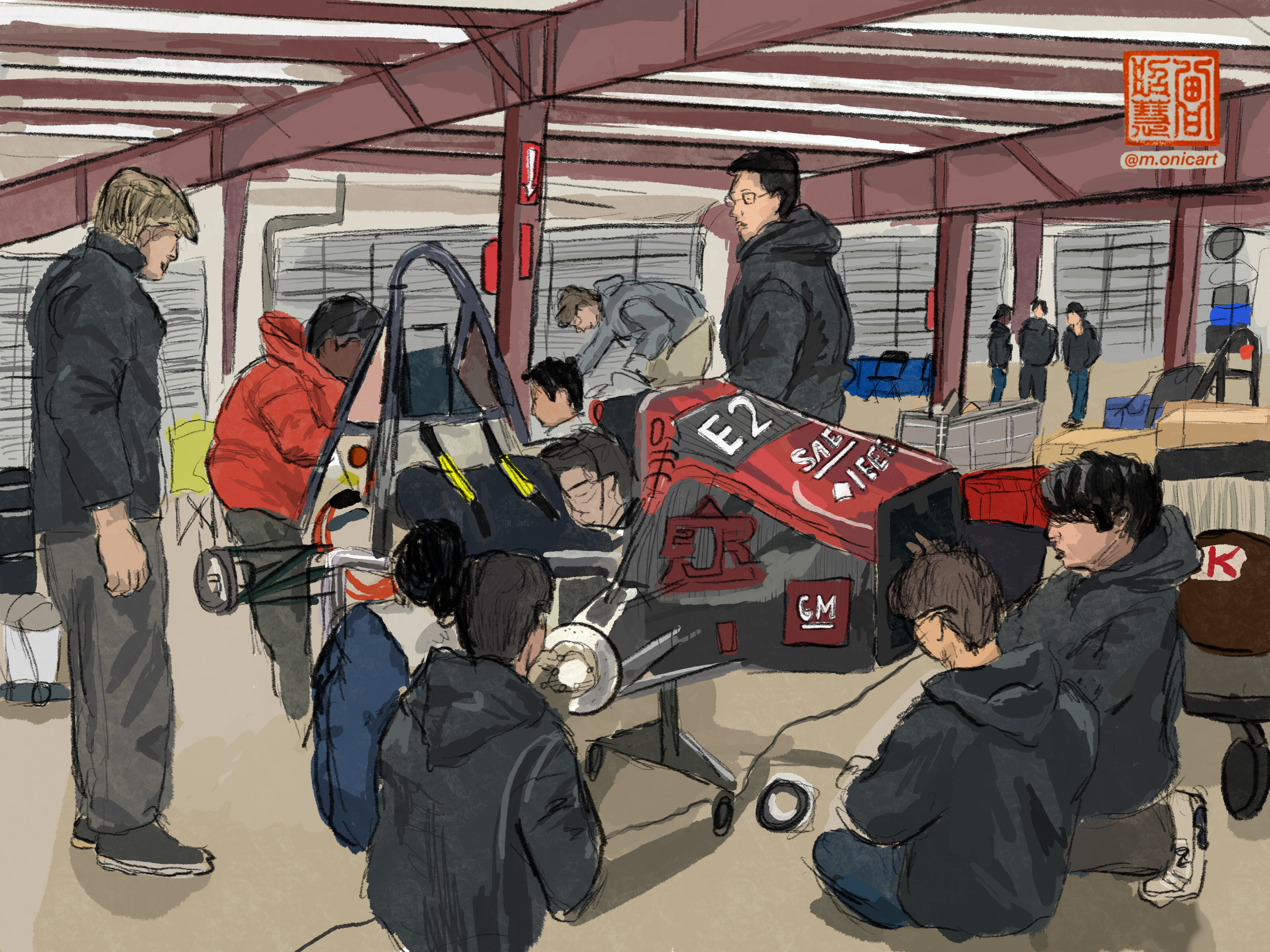
Most of my time is spent coding for MIT’s Formula SAE Electric Vehicle team. Every year, we build a Formula 1 style electric vehicle racecar, and compete in the Formula Hybrid and Formula SAE competitions.
As software lead, I’m responsible for managing my subteam and delivering vehicle controls, board firmware, and data acquisition subsystems. In 2025, we are aiming to create our first driverless car. This is definitely a more ongoing project, but as of Dec 2024 I decided I want to write up some of the design process.
The goal for 2025 is to have a 1/4 scale test vehicle running the entire autonomous stack, outfitted with the computer and sensors we will put on our 2026 car.
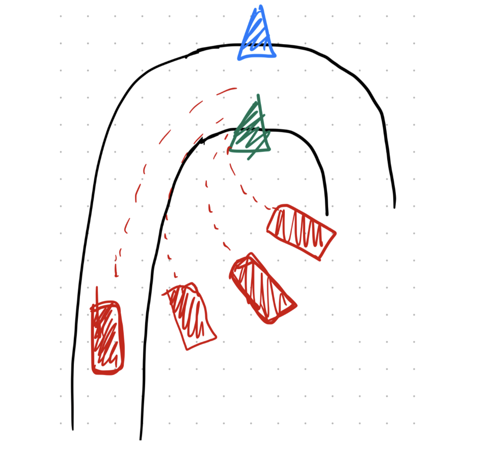
Formula SAE is integrating a driverless component into the competition, phasing in slowly over the next couple years. It will be similar to the Formula SAE Germany style driverless cup competition, in which a car must navigate between blue and yellow cones outlining an autocross style track.
A video of the 2024 Formula Student Germany winning trackdrive can be found here: AMZ’s 2024 FSG winning trackdrive
The main idea is basically: detect the cones and make a plan to navigate through them, keeping the yellow cones on the right and the blue cones on the left.
The cones we have to detect are here: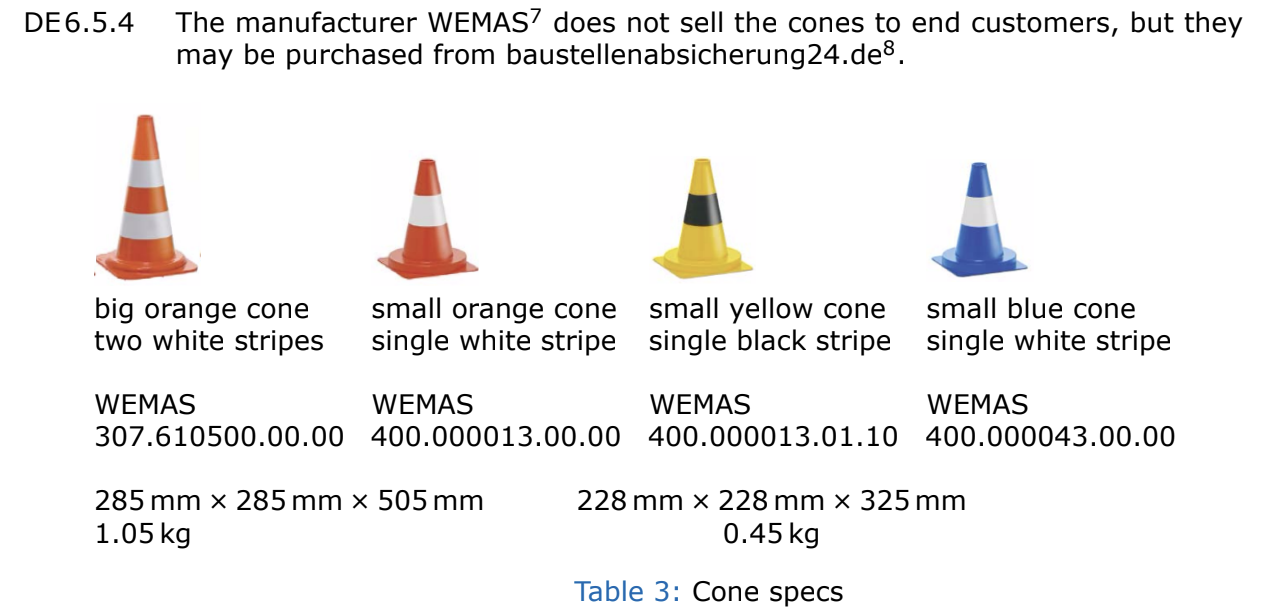
This page is being updated periodically, the design of this car is ongoing.
Designing the Team
I was the software lead for my junior year as well as my senior year, and coming into this year with one year of experience under my belt told me that the team was going to make or break this project, not the technical problems. Lots of other teams’ advice is to think through the structure of the team very carefully, and I definitely agree with them. Division of responsibility for such a large project was absolutely crucial in the beginning months of design, and developing a strict timeline was key.
I started by setting a recruitment goal of 10 new people to design our autonomous software for this year, aiming to recruit into a few subcategories:
- Perception - This is the team responsible for seeing and identifying the cones in the field.
- State Estimation - This is the team (for now one person) responsible for figuring out where we are in the track, given the cones that we see from perception.
- Motion Planning - This is the team that is responsible for figuring out what the next step is: how much do we turn? how fast do we go?
- Controls - This is the team responsible for executing the desired trajectory, mostly low level and motor control knowledge here.
- Infrastructure - This team is responsible for maintaining the architecture of the software and doing all the ROS things.
I thought it was crucial that the autonomous team had a passion for designing a real product: not just something that would sit in simulation. So I recruited the autonomous team just like any other software system on the car, I gave them the same new member project which was to make a little STM32L4 nucleo board perform some simple tasks (communicating over serial and stepping through a state machine). This filtered out a lot of people who were not interested in hardware, which was my goal. I got very lucky to have found a team of amazing 10 people who joined the team this year for autonomous, and were willing to take a gamble on me and the team for this gigantic R&D step that our team had never taken before. I will say that our Formula SAE team as a whole was in a much better position to take this project on this year than before, many teams usually only have 1 or 2 guys writing the software for their entire car. When I was appointed software lead in my junior year, we had 2 people including me. I focused on growing our team to a size where we could take on more R&D projects, and that’s exactly what I did. I now lead a small army of 26 software engineers (10 working on the autonomous car and 16 on the normal car).
Design Requirements
We ran a small kinematic script to derive our initial lookahead distance and FOV requirements. I realized that the most constraining part of executing the trackdrive would be the smallest diameter turn, which is outlined to be 4.5m in diameter. We swept trajectories leading up to the hairpin and calculated the amount of distance in advance we’d have to detect the cone at the apex of the turn in order to achieve our hairpin speed.
Our script gave us our initial design requirements!
- Lookahead distance of 20m
- Horizontal Field of View (FOV) of 120 degrees.
- Minimum pixel height for cone detection should be 20 pixels. This requirement came from existing requirements set by other teams plus some papers.
- Latency from sensor input to actuation should be 350ms.
The key intuition behind these results is that the situation where our lookahead distance is most constrained (longest) is when the car is approaching the hairpin straight on. The situation where our angular FOV (AFOV) is most constrained is when we are approaching the hairpin from a skidpad like angle. This script is beneficial because it ensures our AFOV will allow us to execute skidpad safely.
Sensor choice
Our team knew from the beginning that we wanted both lidar and cameras on our car. It just made sense since both provided critical functionality, and sensor fusion was an interesting problem to the team.
LiDAR
We wanted a mechanical spinning LiDAR sensor because of the added FOV. Luckily, there aren’t that many options on the market, especially since Ouster purchased Velodyne, so we decided to go with the latest Ouster model, the OS1-128. This has 128 vertical channels which is really amazing, especially comparing it to the 32 channel one MIT Driverless lent to us.
Cameras
I learned quite a lot about optics in the last two months. We quickly realized that we would need more than one camera, since you can outfit different specced lenses onto cameras to achieve different FOV’s. We decided we needed to make more specific design requirements for our long and short range systems.
Short Range:
- Working horizontal FOV of 5m (width of the track) at 1.5 m.
- Maximum required lookahead of 6m.
Long Range:
- Working horizontal FOV of 5m at 4m.
- Maximum required lookahead of 20m.
- Minimum pixel resolution of 15 px at 20m.
Equations that ended up being important: $AFOV = 2*arctan(sensor_width/(2 \cdot focal_length))$
$focal_length = min_pixels \cdot lookahead \cdot pixel_size/feature_size$
We used the second equation to spec out what the focal length of our lenses should be for the feature we wanted to detect. We determined that our initial goals were a little unrealistic, and settled for an 8mm lens that provided 15 pixel height at 20m lookahead distance.
Originally we wanted one long range camera and one short range camera for reliability (fewer cameras means fewer opportunities for hardware failure), but we then realized that we’d get something like 40% distortion on our lenses if we used one short range camera. As mentioned earlier, the field of view requirements are what most constrains the short range camera, so we decided to split our short range into two short range cameras that each contribute a portion of the whole short range image.
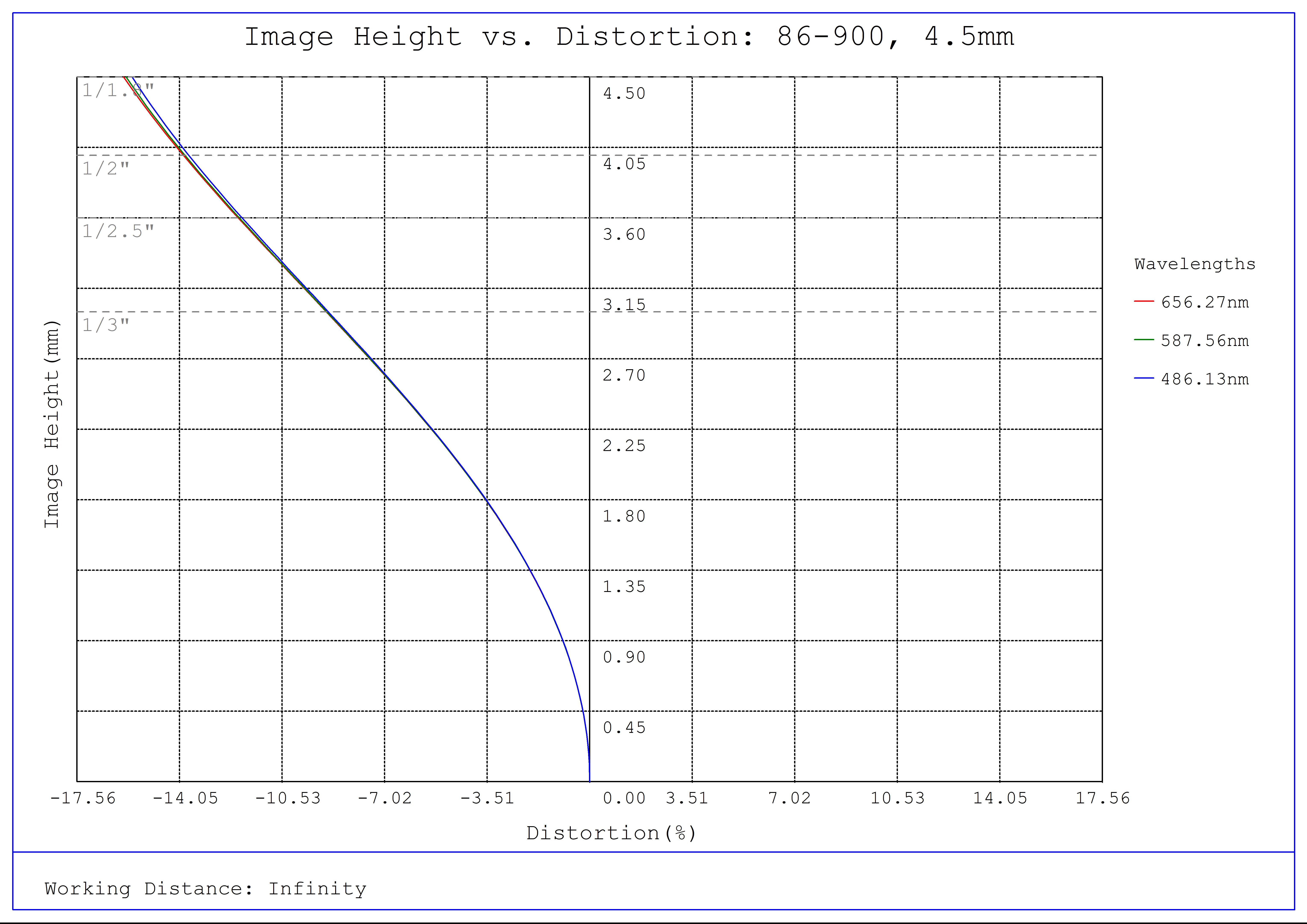
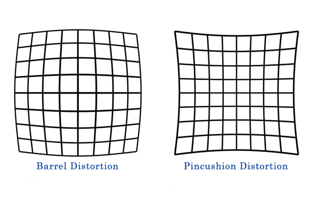
Plot of our short range lens choice distortion, courtesy of Edmund Optics. Our lens will exhibit what is known as barrel distortion since it has a negative percentage of distortion. Our short range camera’s format is f1/1.8, so we achieve around 15% distortion
Optics was this endless rabbit hole I really enjoyed going down, and partnering with Edmund Optics was definitely the right decision. Their website had a ton of technical information packed into each product page, including calculators integrated into each product. For instance the camera products have an imaging lens calculator that pulls up for your required FOV what lens you should select, overall a very seamless customer experience.
We ended up selecting this long range camera with an 8mm focal length lens to achieve 5000 x 3437mm at 2769mm working distance.
We selected two of these short range cameras with a 4.5mm focal length lens to achieve a horizontal FOV of 2500mm at 1582mm working distance. To achieve the full 5000mm FOV, we are going to keystone our cameras (put them at an angle).
Here is a temporary sketch (might replace as we determine the final angle), but for now: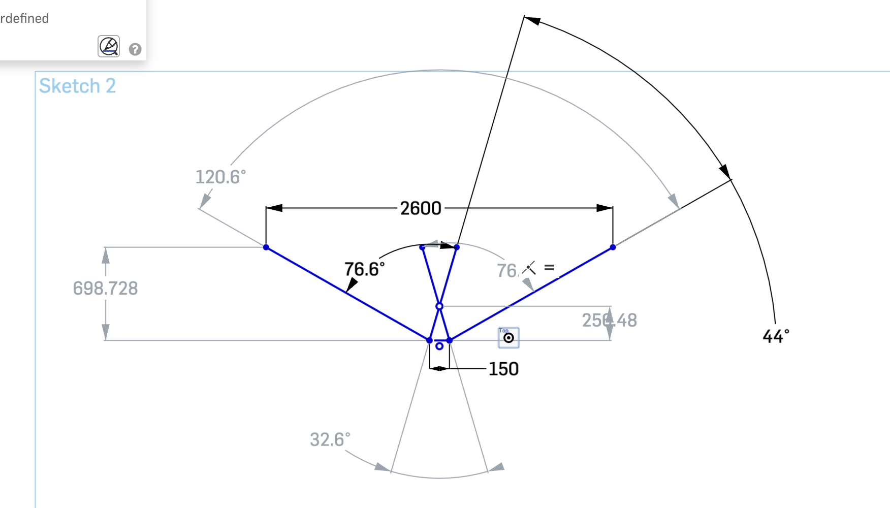
Compute
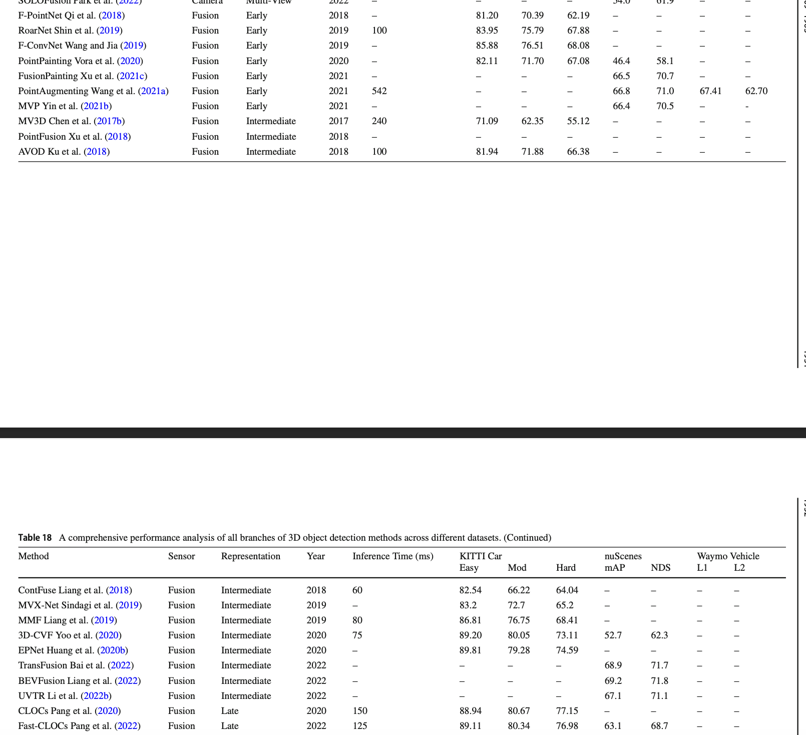
We decided early on to use BevFusion for our sensor fusion model. As opposed to late fusion algorithms, we wanted to choose an intermediate to early fusion model to take advantage of recent machine learning advances. Most of the existing literature for driverless FSAE cars comes from late 2010’s german teams, such as AMZ and even MIT Driverless’s whitepapers. Back then, late fusion was the norm, but now the autonomy world is moving more toward early and intermediate fusion. Our team found this paper written by researchers at The Chinese University of Hong Kong which details current methods of perception and object detection. In particular they had a table that summarized things quite well:
BEVFusion-MIT is among the leading models on nuScenes, achieving ~120ms latency on an Nvidia 3090 (Segments.ai). Performance improves with EA-LSS enhancements while remaining within our 150ms perception latency budget.
For state estimation we will be implementing Graph-SLAM with a Ceres Solver, and motion planning will implement a MPC algorithm. If you’re interested in learning more about our autonomous software design, you can email us at fsae@mit.edu.
All those design choices led us to choose the NVIDIA Orin for our car. We debated building a custom PC but decided against it due to high power draw. The minimum power draw for a custom PC that we could build would be around 250 Watts just for the GPU alone! The Orin draws around 100W, making it ideal for trackdrive conditions along with its very packageable body.
Coming soon: IAP Build Time!
We are planning on doing a bulk of our manufacturing and assembly of our testbed and data collection jig during IAP with the goal of collecting data during IAP!!! If you have any questions at all, please shoot us an email at fsae@mit.edu, or me personally at mochan@mit.edu
because racecar.